With this drawing tool you can draw any lines you like just by moving the mouse pointer to locations to select the start and end points of the lines. The current scene and grid lines are displayed for your orientation. Except for adding new track elements you cannot modify the existing scene – the connection to existing scene elements is handled by different tools.
After some drawing and checking for errors the drawing window may look like this
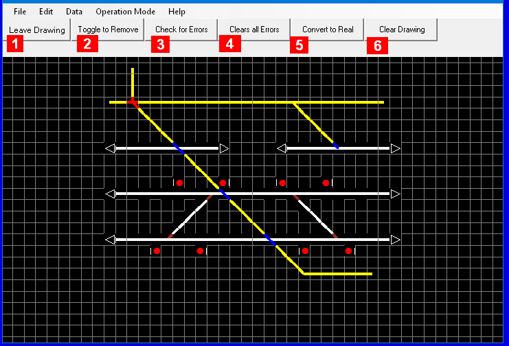
Some details about the buttons above the diagram
-
Leave Drawing: Returns to Editor Level where you can select another tool or leave the Editor altogether.
-
Toggle to Remove/Add: Depending on the text here you can switch to remove drawn lines from the scene or to add new lines to the scene, respectively.
-
Check for Errors: the currently drawn lines are checked, and those in errors will be displayed in red or blue, as indicated below
-
Clears all Errors: checks the drawing for errors and removes all grid elements that would cause conflicts with the current scene, and all grid elements containing lines such that there is no matching track element it could be converted to, leaving a drawing that could be converted without errors
-
Convert to Real: checks the drawing for errors and converts all grid elements that can be converted to track elements such as blocks, simple switches and crossing, which will be added to the scene. Grid elements that cannot be converted will stay as drawings shown in red or blue as indicated below. The new track elements will not be linked among themselves or to other existing track elements already on the scene by this step.
-
Clear Drawing: removes your drawing from the scene.
The following colors are used during drawing
-
Yellow: the lines you have drawn, including the dot in the selected grid element if there is no line yet connected to that – excluding lines that are marked as in error since the last time you checked for errors or are left behind after the drawing was converted to track elements.
-
White: grid elements marked with little white dots to indicate which can be selected as end grid elements to draw a straight line, if a start grid element is active
-
Red: the lines in that grid elements are such that a matching track element does not exist (1)
-
Blue: the grid element occupies a space that is already occupied in the base scene (1)
For more details how to draw, see Drawing on Grids
(1) These colors are shown only after the “Check all Errors” or “Convert to Real” has been performed, for such grid elements that are in error at time the function is invoked.
The drawing tool will draw a line between the start grid and the end grid. Each grid elements can have up to 8 half lines from the center to the edge of the grid element. The convertibility to track elements is determined by the number of these half lines and their relative relations as follows:
-
This single half line will be extended opposite to the other edge to build a full straight line for a track line within a block,
-
The two half lines building a straight line or an angle resembling a boomerang for a track line within a block,
-
Two half lines building a straight line plus one half line building an angle to the straight line other than 90 degrees for a simple switch – or two half lines meeting in the middle in a 90 degree angle and one half line building an angle of 135 degree to the other lines for a Y-switch,
-
Four half lines building two straight lines for a crossing.
-
thru 8. (not valid)
Note, that lines meeting such as to appear connected at the corner of their respective grid elements – such as hidden crossings – will not be connected in any way, since the tool looks for connections across corners if the half lines would build a straight line. However, hidden crossings will be flagged in the error list to alert you of such a situation.
Track lines for a block will be collected in one block as the drawing indicates. However, if such a block would represent a horseshoe curve (a “U” on its side) several blocks are created to avoid a situation that would make the display the direction of a route confusing.