Simple Switches have a straight line and a diverging stub. It is connected to three other track elements, two on each end of the straight line, the third on the diverging stub. Trains can travel on the straight line from end to end, or on the diverging line from one straight end to the diverging line. The speed limit is enforced on the diverging route only.
Y-Switches don’t have a straight line, the “straight” line is diverging – just to the other side. The speed limit is enforced on both routes, but they can be different on each branch.
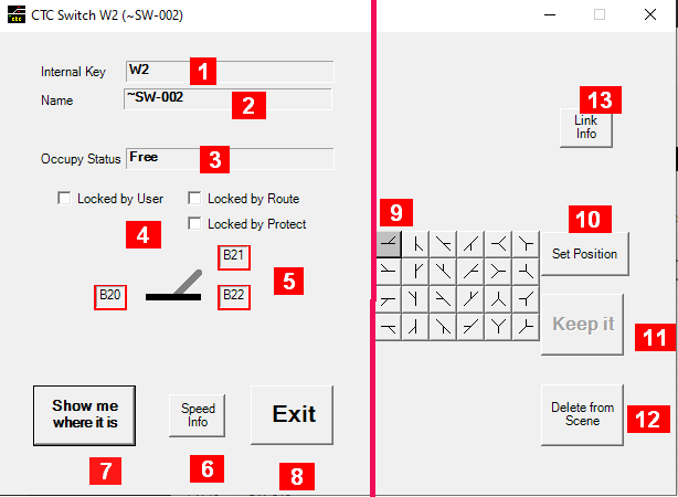
In Run mode, only the portion left of the red separation line of this panel is displayed. In Edit mode, the whole panel is displayed.
Fields common in both modes:
-
Internal Key: a unique non-modifiable identifier provided by the system.
-
Name: an optional identifier. Editable in edit mode.
-
Occupy Status: whether the switch is free, inroute, occupied, in maintenance (display only)
-
Lock info: if anyone checked the switch cannot be thrown. For further information on the type of locks see here. Route Locks and Protect Locks are display only.
-
A graphic showing the switch indicating the status (straight or diverge – or which way for Y-switches). A label at each leg shows the internal key of the element it is connected to – clicking on it will open a window showing the details for that particular element. In Edit mode, a right click will copy this link information into a link maintenance tool from which the connection can be manipulated. Also in Edit mode, a click on the graphic will change the default status of the switch, which is saved in the territory file along with the other data of this switch
-
Speed Info: opens a separate window displaying the speed limit for each train type to obey when the switch is set to diverge (if two columns are shown for switches other than Y-switches, only the left column is used). For Y-switches there is a speed limit for both paths – the same if there is only one column, otherwise the left column is enforced if the path is set to branch to the left, and the right column for the right branch. For all other switches there is no speed limit when the switch is set straight.
-
Show me where it is: activates the main window where a marker has been placed on the switch for you to easy locate (hit <ESC> there to return)
-
Exit: closes this window.
In Edit mode you see also on the right half of the window:
-
A collection of graphics of all 24 possible available switch types, with the current type highlighted. Clicking on one of them here will change the type and update all displays. (1)
-
Set Position: activates the main window with grid lines, where you can place this switch on any free square grid element with a mouse click (hit <ESC> there when done to return)
note: as long as the grid lines appear on the main window , you can return to the main window and repeat the placement again. This will stay active until you hit the “Keep it” button, close this window, or you activate this feature for a different object, at which time the location of this object will be settled. (2) -
Keep it: the switch’s position is now fixed (removing the grid lines on the main window). Without it it can still be changed on the main windows even though you may have done other things. (2)
-
Delete From Scene: Removes this switch from the scene. Objects to which this switch was connected to will have their linkage to this switch removed, resulting to a null linkage there.
-
Link Info Opens a window which shows all linkages from this switch including unused one.
Notes:
-
The diverging link will be moved if necessary. This can result into unexpected paths requiring adjustments of the linkages, like using the swap action within the link maintenance tool
-
For details see here.